Headlight Switch
Modification using
blue LED’s
IMPORTANT NOTICE: The
modifications depicted on these pages are solely my own applications and if you
want to try them, you do it at your own risk. I cannot be held responsible for
any damage or mishap.
Now the first mod of the
2005 modification season J
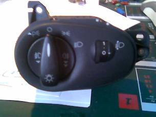
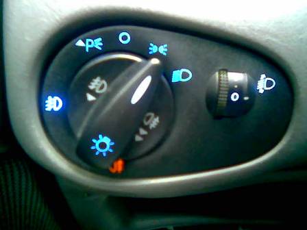
The green illumination of
the headlight switch is annoying. It must be blue! This is a relatively simple
modification. You must notice that there are at least four variants of the
switch: With or without headlamp leveling and with or without panel light
dimmer. Two times two makes four J
The most important point
which makes the level of difficulty of this modification to be moderate is that
the illumination is achieved with ordinary through the hole type 3 mm LED’s.
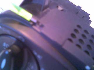
First you must remove the
surrounding panel by removing the 5 screws. Then you must remove the three
screws which hold the switch in place. As a last step you must remove the
electrical connector by depressing a small tab underneath.
The four tabs must be
loosened and the front bezel must be removed.

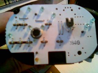
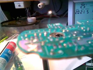
Now after loosening the
four rear tabs, the rear cover must be removed. Take care of the position of
the potentiometer to the right. If you have also the dimmer function there will
be another potentiometer. They must be aligned with the tabs of the front plate
to function correctly. You can see the LED’s.
Yo can simply pull the
board to remove it. You can us a small screwdriver at the sides as a help.
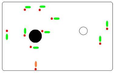
The polarity of the LED’s
is important. Please refer to the diagram at the end of this page.
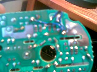
Now you can unsolder and
remove the LED’s. You can leave the orange LED for the rear fog lights or
you can change it as well. Take care of the relatively delicate solder points
of the board. They can easily be damaged by the heat of your soldering gun. The
old green LED’s will probably broke during unsoldering. After
unsoldering, yo can solder the new LED’s in. Take care: Polarity is
important!!!
If you want you can use
two 1.5 batteries in series or a 5 V power source with a 1k resistor in series
to check whether the LED’s are OK and soldered correctly in place. Maybe
you can use e few drops of cyanoacrylate glue for the mechanical stability of
the LED’s. After this you can put the parts of the switch together and
mount it in place.
Here are the LED
polarities shown.